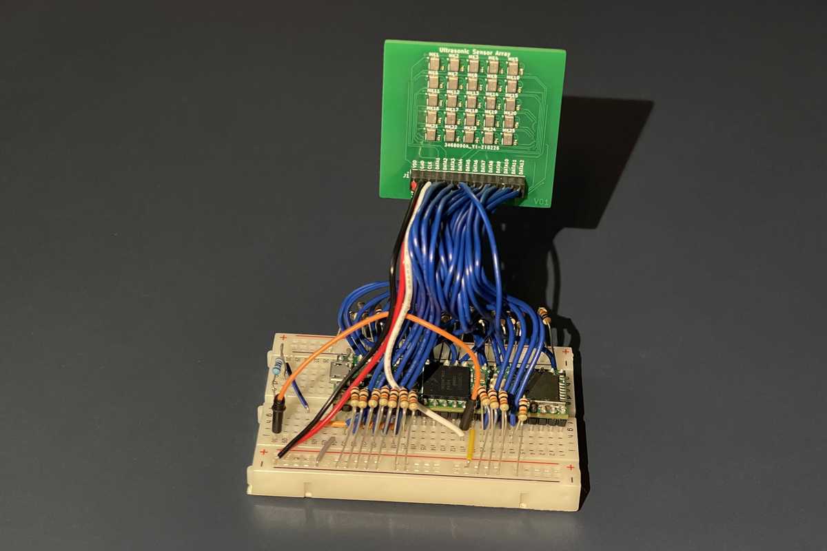
I designed and created this ultrasonic recording system for a high school research project. It consists of an array of 25 microphones working together to create a directional recording device capable of detecting audible sound and ultrasound. The goal of this project was to create a cheap system that can be built at home that is capable of recording ultrasonic sounds. I also hoped to explore and experiment with important ideas in signal processing, electronics, and antennas.
You can read the full paper here, but note that this paper is not peer reviewed, so I am unable to verify any of the information in it.
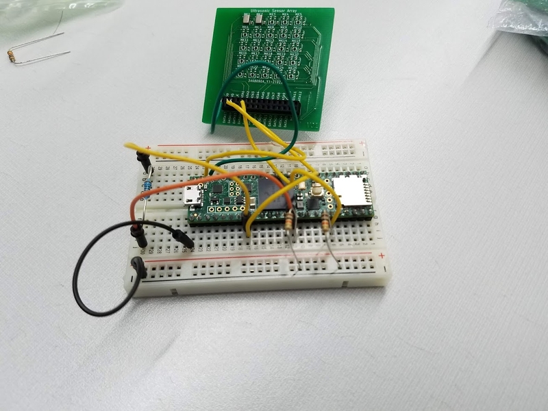
The recording device consists of a Teensy 4.1 microcontroller, a custom circuit board with microphones, and some supporting electronics. The microphones used were MEMS microphones, which are the same type used in cell phones. While these tend to not be the most sensitive and accurate, their small size was ideal for creating a closely spaced array that is required for high frequencies. They were also relatively easy to integrate into the device.
The Software
I wrote programs for both the design and operation of the device. One of the key aspects of the design of the device is the geometrical arrangement of the microphones that form the array. Different arrangements result will change how sensitive the device is to sound coming from different directions, so finding the optimal arrangement was key. One tool used to compare geometries is the array pattern, which is a graph that shows how sensitive the array is to sound coming from different directions. I created a Python program to generate the antenna pattern for a given array geometry. This aspect of the project was more complex than I expected because of the physics and mathematics involved and the details of the Python implementation. Because of this, I was unable to understand this aspect of the project as well as I would have liked, and ended up choosing a square grid configuration because the performance was acceptable and it made the circuit board design simple.
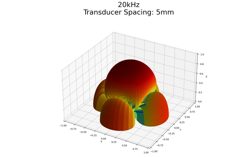
The microcontroller code was also more difficult to write than expected. This program needs to read the data from the microphones and send it over USB to a computer for processing. With the microphones running at the fastest rate possible, the device produces 125 megabits (16 megabytes) of audio data every second, so fast hardware and optimized code are required. I was never able to get the program to run fast enough to sample the microphones at the maximum rate, and even at slower speeds I ran into problems transmitting the data consistently.
In the initial proposal for the project, I had planned to develop a real time spectrograph to display the microphone data, but this was never implemented because of time constraints.
The Results
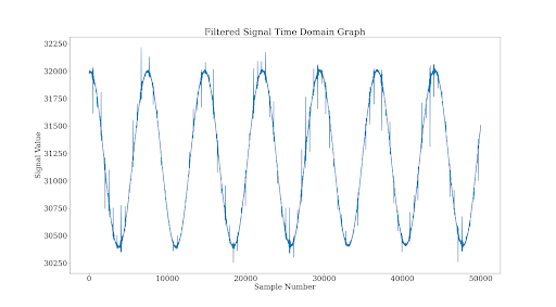
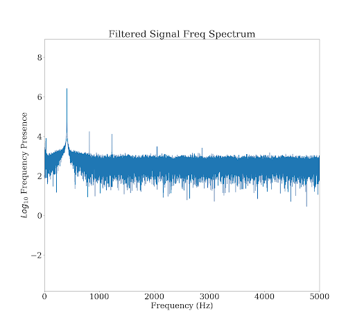
The device was capable of recording both audible sound and ultrasonic sound, but a problem likely caused by inconsistent data transmission between the microcontroller and the computer prevents the device from being accurate and useful in its current form. While writing the code for the microcontroller, I found that it would transmit about 500 samples at the necessary speed and then take much longer to transmit the next few samples, before returning to the normal speed. This causes data to be lost, which results in spikes in the signal and new frequencies appearing in the frequency spectrum.
